
Extension of operation temperature range to 200°C enabled by Al/Cu wire bonds
Wednesday, 19 December, 2012
The demand for an extension of the operation temperature range to 200°C has been promoted by several trends: first, the use of the combustion engine cooling system for cooling power electronic components in hybrid passenger cars requires an extension of the maximum junction temperature since the cooling liquid temperature can be as high as 110-120°C; second, the wide bandgap materials such as SiC and GaN are capable of high-temperature operation and therefore demand for a packaging technology for higher operation temperatures; and last but not least, the higher current capability provided by the extended temperature range increases the power density without additional improvements of the power electronic system.
However, the development of power electronic devices with a maximum junction temperature of 200°C must be accompanied by a significant increase of lifetime for the packaging technology. Applying classical lifetime models, this reliability increase must be in the range of a factor of 5.
Power modules for junction temperatures up to 175°C
The latest generations of IGBTs and freewheeling diodes are already rated for maximum junction temperatures of 175°C. This increase of 25°C with respect to the former traditional junction temperature limit of 150°C already required improvement of the packaging technology: the elimination of solder fatigue and the enhancement of Al wire bond reliability.
These improvements were implemented in the first 100% solder-free module SKiM63/93 presented in 2008. Solder fatigue is eliminated by the architecture without base plate, which eliminated both the base plate and the base plate solder interface on the one hand and by replacing the chip solder interface by a Ag sinter diffusion layer on the other. This power module design requires a reliable pressure contact technology and spring contacts for the control contacts - both technologies have been successfully invented and validated in years of field experience by Semikron. Additionally, the reliability of the Al wire bonds had to be improved to enhance the lifetime for 175°C maximum junction temperature. This was achieved by an optimisation of the wire bond geometry. Increasing the loop height of the wire bond can significantly increase the lifetime during repetitive temperature swings in active power cycling tests. While the reliability enhancement of Al wire bonds with increased aspect ratio (ie, the ratio of loop height to the distance between bond stitches) is sufficient for maximal junction temperatures up to 175°, a further enhancement is required to fulfil the demand for an extended operation temperature up to 200°C.
Al-clad Cu wire bonds
Heraeus as a major supplier of wire bond material had started to investigate the use of composite materials for wire bonding already in the 1980s. The increase of the number of cycles to failure for Al-clad Cu ribbon bonds shifted this technology back into focus in 2007. Consequently, a technology development for fabricating Al-clad Cu wire bond material with a circular cross-section was started at Heraeus.
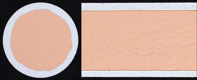
Figure 1 shows a cross-section of the Al-clad Cu wire bond supplied by Heraeus for this investigation. The material consists of 60-70% Cu by volume, which is equivalent to an Al layer thickness of 25-35 µm around a 230-250 µm Cu core for a 300 µm wire. The high fraction of Cu requires finetuned tailoring of mechanical properties for different wire bonding applications. For this reason, two different versions have been tested:
Type A is the robust version of this Al-clad Cu wire with harder Al material and higher yield strength. This material combination shows the maximum reliability in mechanical cycling due to high work dissipation capability. The full effect can be utilised in bonding on robust semiconductor surfaces or passive devices.
Type B is the softer version of Al/Cu wire optimised for better bondability. With softer Al coat and lower yield strength, type B provides a wider bond window and lowers the risk of chip damage. The mechanical cycling reliability is lower than for type A, but still expected to be higher than for pure Al. Type B is more appropriate for sensitive devices.
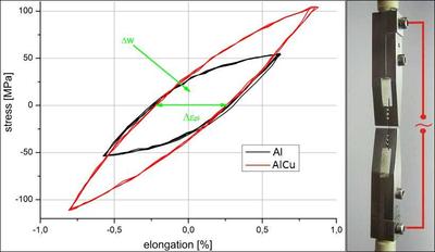
Uniaxial mechanical cycling was performed to show the difference between the standard Al wire and the Al-clad Cu wire. A several-millimetre-long piece of wire was fixed in a measuring device and exposed to periodical stress with defined plastic strain. Two criteria for the deformation process have been applied: constant elongation and constant dissipated work. In Figure 2 the elongation is shown on the X-axis, the corresponding dissipated work is the integral of elongation over related stress, shown as the area within the hysteresis curve. One characteristic difference between both materials is the higher stress at the same elongation for the Al-clad Cu wire. The enclosed area is ‘rotated’ in Y-axis direction for the Al/Cu wire.
The numbers of mechanical cycles to failure at related strain build the S-N curves shown in Figure 3. The results confirm that Al-clad Cu wire is able to withstand a higher number of mechanical cycles before breaking compared to Al wire.
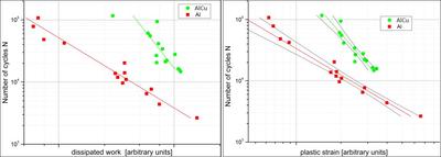
Figure 3: S-N curve for Al and Al-clad Cu wire (type B) for plastic strain (left) and dissipated work (right).
Power cycling results for Al-clad Cu wire bonds
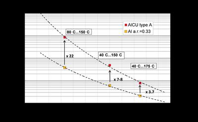
A SKiM63 module was selected as the vehicle for the power cycling test. In a first test series the type A Al-clad Cu wire was compared to the standard Al wire. To avoid heel cracking, bond loops with comparable aspect ratios of approx 0.32 were generated for both wire materials. As the type A wire was still too hard to be successfully bonded onto sensitive IGBT dies, tests could only be performed on diodes. The power cycling was conducted with three different junction temperature swings and all tests were set with relatively small power-on times (1-2 s) to reduce overall test duration.
In a second test series, the type B Al/Cu wire was investigated. Due to the increased softness of the composite material, the bonding process was less critical and also IGBT chips could be successfully bonded. Thus, power cycling tests for the type B wire were performed on the IGBT chips. As test duration of the ∆Tj=70K test was expected to be very long, only test conditions ∆Tj=110K and ∆Tj=135K were selected for the characterisation of type B wire. Table 1 shows the corresponding test results in comparison to the diode results of type A Al/Cu wire and the standard pure Al wire.
| ∆Tj | Al/Cu type A on diode | Al/Cu Type B on IGBT | Al on diode | |
| a) | 70K | 8,500,000 | ... | 380,000 |
| b) | 110K | 486,000 | 257,000 | 60,000 |
| c) | 135K | 77,000 | 68,000 | 21,000 |
Although the bonding process is less critical for the softer type B version of the Al/Cu wire, its power cycling capability is significantly reduced compared to the original type A version. Instead of 77,000 cycles to failure, only 68,000 cycles could be achieved with the type B wire in the ∆Tj=135K test. The reduction is even more pronounced for the ∆Tj=110K test: the type B wire failed after 257,000 cycles. Compared to the type A wire test result of 486,000 cycles, this means a reduction of almost 50%. Nevertheless, if compared to the standard Al-wire bonds there is still a huge advantage in load cycling capability (factor >4) which is expected to further increase at smaller temperature swings, which are more relevant for real applications.
It should be emphasised that the presented results were obtained on very first samples of the novel composite material and no detailed bond process optimisation was conducted. Further optimisation of the bonding wire material and the corresponding bonding parameters is expected to allow a better trade-off between the excellent wire bond lifetime and the compatibility to establish a stable wire bond process.
Advantages of Al-clad Cu wire bonds
Pure Cu wire bonds have been proposed as an alternative to pure Al wire bonds for packages of devices with a maximum junction temperature of 200°C. The implementation of pure Cu heavy wire bonds requires the change of chip metallisation from Al to Cu, which is associated with severe problems. Cu contacts on silicon devices are subjected to diffusion and corrosion. Diffusion of Cu into the semiconductor device can interfere with the electrical function of the device. Corrosion can also compromise the device functionality if conductive corrosion products interact with the high electrical fields at the passivation edges of high blocking devices. Both problems have to be solved by a suitable design of the contact metallisation.
Al-clad Cu wire bonds, however, are compatible with the state-of-the-art aluminium metallisation on the top side contact of power devices. They can be applied with minor changes to the bond parameters and do not even require a special bond tool. Therefore, Al-clad Cu wire bonds are ideally suited to increase the wire bond lifetime without the drawback of a new chip top side metallisation.
Al-clad Cu wire bonds versus Semikron SKiN-technology
The SKiN technology which replaces the wire bonds by a flexible power layer is a new design approach to address the future needs of power electronics - higher operating temperatures, integration, elimination of thermal grease interface and reliability. The SKiN-technology is a revolutionary progress in technology. It combines a reduction in thermal resistance and an improved internal parasitic inductance with the enhanced reliability of a wire bond free package technology platform. However, in order to exploit the advantages emerging from this new technology, the module outline and system configuration must be adapted to this new packaging platform.
Al-clad Cu wire bonds are suited to replace standard Al heavy wire bond with enhanced Al-clad Cu wires. This replacement does not require additional changes to the module design and can be implemented in any existing module with wire bonded chips. In combination with a replacement of solder die attach by more reliable technologies as Ag diffusion sintering or transient liquid phase bonding (TLPB), modules with an extended operation temperature range are feasible without impairing the lifetime expectation. Therefore, Al-clad Cu wire bonds allow an evolution of existing module designs and thus enable reliability enhancement in existing system designs.
It should also be noted that comparison of power cycling lifetime is typically related to a fixed temperature swing. This methodology is acceptable for modules with a comparable thermal resistance. However, when comparing modules with significant differences in thermal resistance (SKiN exhibits a more than 20% reduced thermal resistance compared to classical module) it must be emphasised that a higher current density is required for the module with the better thermal resistance to generate the same temperature swing. Based on a constant current density, a module with a higher thermal resistance must feature a much higher lifetime in active power cycling to achieve the same performance.
Both technologies, Al-clad Cu wire bonds and the SKiN technology, are required to meet the challenges of improving the energy generation and distribution and to enhance the efficiency of electrical power consumption.
Encryption: the key to embedded security
Designers of embedded systems must keep up with the latest cyber threats and develop long-lasting...
A replacement for traditional motors could enhance next-gen robots
Researchers at Stanford have designed a spring-assisted actuator — a device that can...
A leap towards computers with light-speed capabilities
Scientists have created a reprogrammable light-based processor that could help enable successful...


")