Antenna simplifies LTE indoor coverage
By Rolland Zhang, Agilent Technologies
Wednesday, 30 May, 2012
According to recent statistics, more than 80% of all mobile data calls are initiated inside a building, whether an office, airport, railway station, stadium or home. As a result, it is absolutely critical for service providers to provide both good coverage and quality of service inside buildings.
How well they meet this goal will ultimately determine which one emerges as the market leader in the 4G era.
In the past, operators provided indoor coverage by using outdoor macro sites. The goal was to provide just enough coverage for voice calls. Unfortunately, this ‘just enough’ approach to coverage no longer presents a viable solution.
While an acceptable voice call needs only about a 9 dB signal-to-noise ratio, this is not the case for a data connection. To achieve good data throughput, the SNR should be better than 15 dB.
As an example, consider the long term evolution (LTE) standard, which employs 16QAM and 64QAM to achieve higher throughput. To achieve the desired data connection speed, both the LTE uplink and downlink must maintain a better SNR - something that is almost impossible to achieve using outdoor macro sites.
Because of this, distributed antenna systems (DASs) are now being deployed to provide indoor coverage.
Deployment of indoor DASs can be extremely challenging, both from a hardware perspective and an over-the-air signal quality perspective. To begin with, the cable and antenna system for an indoor DAS is very complicated.
It includes many RF components like attenuators, splitters, combiners, diplexers, bidirectional amplifiers, filters and even a fibre system (eg, a passive optical network), which macro sites typically don’t use. Mitigating interference also presents a challenge for DASs, since inside buildings signals are affected by reflections.
Many DASs share the same infrastructure, which makes indoor systems prone to co-channel, adjacent channel, external (illegal transmitters) and inter-modulation interference.
When deploying an indoor DAS a number of different tests and optimisation tasks must be performed, including:
-
Indoor coverage test. One of the key tasks that must be performed when deploying a DAS is to conduct a site survey. Doing so allows the technician to decide where to put the system's transmitters and antennas. This location is crucial as it must enable optimum coverage and avoid interference from other networks. The test generally requires one signal generator that is connected to the antenna under test. The generator sends a continuous wave signal to the antenna where a spectrum analyser or scanning receiver is used to measure the signal's range.
-
Leaky coax testing for tunnel coverage. Coverage testing is particularly essential for a leaky coax, a special type of DAS. A leaky coax is made by cutting predefined slots on a cable shield to allow signals to leak out of the cable and is used to cover the long tunnels (generally 10s of kilometres long) on train and subway tracks. Ensuring coverage in these tunnels is critical because train control signals, public safety communications and commercial communications all share the same leaky coax cable.
Two performance indicators that are key for a leaky coax are cable loss and signal coupling factor. Measurement of these indicators is accomplished by sending one or a few CW signals from one end of the cable along the tunnel. The signal strength is then recorded using a spectrum analyser. This test is critical to perform since people's lives are on the line, but because there are many cables that need to be tested in a single tunnel, it can be quite tedious.
Return loss or voltage standing wave ratio (VSWR) are two performance indicators that are commonly used to evaluate cable and antenna systems. This is especially true for 3G and 4G DASs, which have more RF components, each of which can either add loss or create reflection in the system.
If the system is not properly installed, matched and tested, the resulting reflection may reduce coverage and create interference.
For instance, an unacceptably high return loss on a transmit path will reduce the amount of energy transmitted OTA on the downlink. In this situation, the SNR of the downlink is degraded, causing the mobile phone to think it is far away from a base station. In response, it increases transmit power to make the uplink RSSI higher, setting off an uplink interference alarm.
As previously mentioned, LTE requires much higher SNR to provide higher data throughput. Because of this, poor cable and antenna system performance will have a much bigger impact on an LTE network than it will on 2G or even 3G networks.
DASs provide indoor coverage for LTE networks, but they usually have much bigger loss than a standard outdoor site due to their longer cables, combiners, splitters and couplers.
The loss of the system degrades the SNR, which can trigger the mobile to transmit too much power and bring up the noise floor. The higher noise floor degrades the quality of service and system capacity. Therefore, it is essential to make sure the indoor system is properly designed and tested.
When it comes to determining the health of a signal, SNR is the key performance indicator.
Many forms of unwanted signals exist inside buildings today. These may include: co-channel and adjacent channel interference, active and passive intermodulation, external interference from transmitters not registered in the network (eg, BDA/repeater), multipath interference, and penetration interference to/from outside.
Maintaining good SNR across the building is, therefore, essential to achieving good data throughput.
Key to streamlining indoor DAS testing is to use an integrated, multiple functional handheld RF analyser that is flexible enough to quickly and consistently perform the required measurements outlined earlier.
The integrated nature of the instrument gives engineers access to multiple test functions in one tool. Portability is also critical since DAS testing is conducted in the field.
Therefore, the handheld instrument should be lightweight, have a small size and be weather resistant, rugged and battery powered.

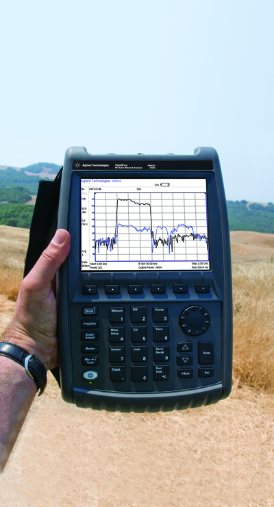
One such instrument that meets this criterion is the FieldFox RF analyser (Figure 1). It integrates a number of different functions including a built-in QuickCal that allows users to make cable and antenna measurement without having to carry a calibration kit, and a built-in independent CW generator that is convenient for testing indoor coverage.
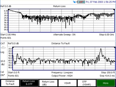
The QuickCal feature greatly simplifies field test work and improves measurement repeatability. A cable and antenna analyser provide return loss, distance-to-fault, insertion loss and VSWR measurements, as well as one-port cable loss measurements up to 30 dB (Figure 2).
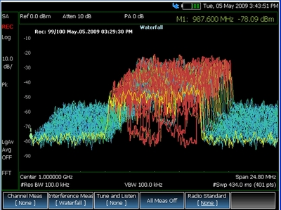
Two-port insertion loss measurements up to 100 dB loss or antenna isolation can also be made. Additionally, FieldFox provides a spectrum analyser with a dynamic range up to 96 dBc, enabling it to find small unwanted signals in the presence of large network downlink signals, and an interference analyser with record and playback to more quickly capture intermittent signals (Figure 3).
An accurate broadband power meter provides good calibration of transmitters, while a vector voltmeter is suitable for measuring multiple-input multiple-output (MIMO) and other phase array smart antennas in the field.


With deployment of LTE, service providers are looking to integrate indoor DASs into the network. While DASs offer service providers a way to provide users with indoor coverage, that benefit comes at a price - the introduction of a number of unique complexities and challenges.
Use of an integrated, handheld RF analyser like FieldFox offers engineers an optimal means of addressing these challenges.
Using it not only streamlines DAS testing and leaky coax test, but it is also improves field test efficiency and measurement reliability.
Light reshapes semiconductors for advanced optical devices
Researchers have shown how light reshapes Janus semiconductors at the atomic scale, enabling...
Novel method to grow ultrathin semiconductors on electronics
Researchers have developed a technique that could speed up the development of next-generation...
Blue LEDs developed to enhance display performance
Researchers have developed a new method for manufacturing light-emitting diodes (LEDs) that emit...


