Panel appeal: lighting the way to good design

The design of professional and consumer electronics front panel indicator lights is a key part of the user experience of the equipment. It’s the first thing users see when they switch on, and the reliability, accuracy and helpfulness of the messages these indicators convey will have a big impact on the way users interact with the system. Michael Finn* and Adrian Rawlinson^ review the most recent developments in the technologies for bringing light to the front panel.
Where front panel status indicators are concerned, designers have available numerous options: LED, neon, incandescent or halogen. Another approach is to use light pipes, which can deliver light reliably to front panels over long distances, when conditions preclude the fitting of indicators directly to the front panel — corrosive or flammable atmospheres, or where restrictions apply with regard to static discharge or EMI, are examples.
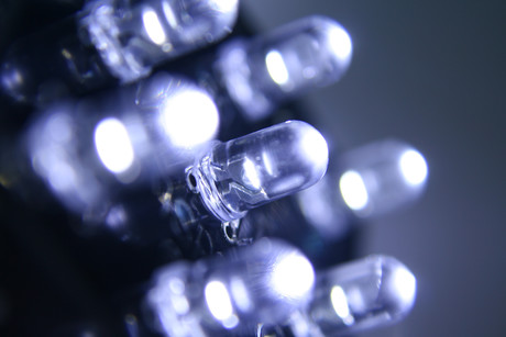
LED panel indicators are becoming increasingly popular because they have the advantages of long life span, low energy consumption, minimal heat generation and superior reliability. They are also more durable and shock resistant, and have faster turn on/off speed than other types of illumination. Although specific design considerations may vary, typically, a standard LED panel mount indicator contains an LED light source, housing and wire leads. The connectors and mounting hardware are often added as an option to enhance the design and ease installation — and there are lots of options to choose from.
In addition to the popular green, red, amber, yellow, orange, blue or white single-colour LEDs, bicolour indicators are available. Red and green are most commonly used, and by lighting up both LED chips, it creates yellow or orange-yellow as a third mixing colour.
What lens option you choose will be central to the visual performance of the LED. LED lenses are typically available as ‘clear’, ‘tinted’ and ‘diffused’, with sizes ranging from 3 up to 25 mm. Viewing angles will vary from 10 to 130°, depending on application requirements. A wide viewing angle means that the indication is more likely to be visible wherever the operator is standing, but narrower viewing angles will ensure a brighter indication.
Different LED housings are designed to match the panel profile or give a better aesthetic appearance. Again, there are quite a few indicator housing materials to choose from, including a variety of plastics (nylon, polycarbonate, etc) and metals (stainless steel, copper, anodised aluminium, etc), all of which can be IP67 protected, depending on the environmental conditions.
If the front panel is adjacent to the PCB, the panel indicator can be soldered directly to it, but if this is not the case, a wire lead will be needed to power the LED. The most common wire leads used are UL approved wires of gauges 16, 24 and 26 AWG.
The mounting methods are either push-through type or secured via a lock washer and nut. The nut is attached from the rear of the panel to secure the indicator — an arrangement typically used when the panel is subject to vibration. Connector options are either factory standard or customer specific and are generally designed to make installation convenient and easy.
Flexible light pipes
Flexible light pipes deliver light remotely from a PCB to the panel user interface via an optical core. Transmission distances can be as much as 100 m with minimum attenuation, as opposed to copper wire-based connections, which would introduce considerable resistance over this distance.
Since the optical media is non-conductive, the PCB-located LEDs are fully protected against induced currents and any EMI effects associated with lengthy PCB-to-panel wiring. Moreover, this arrangement is a safer alternative to panel-located LEDs where flammable vapours and gases may be present in the vicinity of the panel.
A flexible light pipe assembly typically contains a lens cap, an optical core and an adapter for the core attachment. The adapters are located on the PCB directly over the LED, and their styles vary depending on requirements for right angle, vertical mounting and so on.
The lens cap can be inserted from the front or rear of the panel and attached directly to the adapter to complete the set-up. There is a lot to choose from in terms of lens size and style, but an IP67 rated housing, made either of polycarbonate or metal, provides a more robust format that is dustproof and watertight, and therefore better suited to harsh industrial environments.
As to the optical core, the typical sizes are 2 mm (1 mm core) and 3 mm (2 mm core). Special 2 mm (1.5 mm core) and 3 mm extra flex (2 mm core) materials are available from Bivar for users who need increased brightness over regular 1 mm core and an easier bending characteristic than the 3 mm. The optical core can be trimmed to any length with no precise core cutting technique needed, and is easily routed via multiple bends if necessary.
The product types and installation systems described above are all available from manufacturers Bivar and Marl, two companies that have formed an international optoelectronics partnership operating across three continents.
The companies can provide semicustomised configurations on a short lead time based on components from their large combined standard product offering. The LEDs supplied by the partnership operate from 8–48 V AC/DC supplies, thus avoiding the need for AC-to-DC power conversion and removing polarity reversal concerns.
Light reshapes semiconductors for advanced optical devices
Researchers have shown how light reshapes Janus semiconductors at the atomic scale, enabling...
Novel method to grow ultrathin semiconductors on electronics
Researchers have developed a technique that could speed up the development of next-generation...
Blue LEDs developed to enhance display performance
Researchers have developed a new method for manufacturing light-emitting diodes (LEDs) that emit...


