
Two filters are better than one

More and more devices on the power grid must function smoothly without interfering with each other. This is not so easy, since switching power supplies and highly clocked integrated circuits are used in almost all electronic devices. EMC filters can help here.
Electromagnetic compatibility (EMC) has become an indispensable quality feature of any electronic device. The manufacturer must indicate the conformity of the device with the protective objectives of the EMC directive by a declaration of conformity and by affixing the CE mark on the device and also on the packaging. As a result, the manufacturer assumes the responsibility before the legislator for compliance with the interference emission and immunity requirements applicable to the device.
Source – Sinc – Coupling
The usual interference coupling model is based on the terms interference source, coupling path and interference sinc. The equipment that generates interference is referred to as a source of interference; the equipment that is affected is referred to as an interference sinc. In order for the source to influence the sinc, the interference must reach the sinc to be able to act there as a disturbance variable. The path between source and sinc is called coupling or coupling path.
Types of interference
In order to be able to guarantee a high EMC at all, the potential interference mechanisms must be known. In addition to natural sources of interference (eg, lightning), there are basically four different types of coupling:
- Galvanic (impedance coupling): Coupling of two circuits via a common current path.
- Capacitive: Coupling of two circuits via an alternating electric field. The capacitive coupling concerns in particular the high frequency range.
- Inductive: Coupling of two circuits via an alternating magnetic field. Inductive coupling occurs in the low-frequency range.
- Radiation: It refers to the emission of wave fields with electric and magnetic field strength.
A distinction is made between dynamic and static interference (mostly electromagnetic fields). The same applies to interference between conducted and non-conducted interference. The galvanic or impedance coupling is wired. All others are based on electromagnetic wave fields.
Countermeasures
It makes sense to pay attention to EMC problems at the earliest possible design phase. Many problems can be avoided by a skilful interpretation of the design. In particular, disturbances caused by radiation coupling can only be compensated for retrospectively at high costs. Conducted interference is reduced most efficiently by means of mains filters.
Elements
An EMC line filter is usually a low pass filter. It has no influence on the mains frequency (50/60 Hz), but attenuates high-frequency interference (>10 kHz).
The filter is an LC network consisting of X and Y suppression capacitors (C) and a current-compensated choke (L).
A current-compensated choke has two counter-rotating windings with an identical number of windings on a toroidal core. This design compensates for the magnetic flux generated by the load current. Only the asymmetrical interference (common mode) is attenuated.
There are two different types of interference suppression capacitors — called X and Y. X capacitors attenuate the differential-mode interference signals between phase (L) and neutral (N). For high-frequency energy, the capacitor acts like a short circuit.
X capacitors are mostly self-healing types of metal paper or polyester. For this reason, they can withstand a high surge voltage. The capacitor can lose some of its capacity, but the insulation remains. A larger capacity leads to a higher attenuation loss.
Y capacitors attenuate the common-mode interference signals between L/N and PE. High-frequency energy, which flows simultaneously on both lines, is dissipated by the capacitor to earth (PE).

Multi-stage filters
In practice, it is quite possible that the attenuation is not yet sufficient despite the use of a filter. In such cases, several filter stages optimised for the specific interference signals are then connected in series, which in interaction significantly improve attenuation in both differential and common-mode interference. Usually you get very good results with a double-stage filter. However, triple-stage filters are also conceivable, feasible and available.

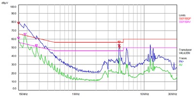
Comparison mains filter: single-stage vs double-stage
The following is a comparison of three power entry modules with fuse holders from SCHURTER: the models DD11, DD12 and DD14. Model DD11 does not have an integrated EMC filter. The DD12 uses a single-stage filter and the new model DD14 has a double-stage filter. A commercially available switching power supply with an output of around 150 W for lighting was used as a source of interference for this test.


Conclusion
In the measurement setup, the three products mentioned are measured under load and the emissions are recorded in accordance with the EMC requirements. The test clearly shows that this load must not be operated without a filter (DD11). The emission limits are exceeded in various frequency ranges. Even the use of a single-stage filter (DD12) is not yet adequate to sufficiently attenuate the interference. Only the use of the double-stage filter (DD14) ensures that the limit values for interference emissions are maintained over the entire frequency range.
However, there is good news for users of the SCHURTER DD11 and DD12 models if they suffer from EMC problems. All models have the same installation dimensions except for the installation depth. They are therefore easy and simple to replace.
View more EMC product solutions from SCHURTER here.
New computational method predicts semiconductor properties
A study led by EPFL researchers has introduced a new computational method that predicts the...
Single unit displays flexibility of modular system
Researchers at Fraunhofer Institute for Photonic Microsystems IPMS have developed a method that...
3D-printed copper plate could transform data centre cooling
If used to cool an entire data centre, the technology would contribute only about 1.1% of the...

")
