
Test and measurement in 2013: the evolution of wireless tools
Wednesday, 13 February, 2013
The major trend for test and measurement in 2013 will be a move to testing by wireless.
The automation of more processes and operations in today’s factories and commercial buildings is helping to reduce energy consumption and increase safety and productivity. However, automation also means more complexity for the technicians who maintain and troubleshoot the systems.
There are two major difficulties facing technicians in today’s automated environment. While technicians need to be able to test a wide range of variables to maintain and troubleshoot the systems, they also have too many tools performing too many functions. For example, if a technician is measuring a transmitter on the back of a pressure gauge, they might also need to manipulate controls on the panel. That requires another set of hands just to hold a tool.
Henk Van Velze, managing director, Fluke Australia, said, “In 2013, we will see an increase in the use of wireless tools for test and measurement. Wireless test tools are particularly valuable in ensuring the safety of technicians in hazardous environments, letting them watch readings from a safe distance.
“Another benefit of wireless tools is the ability to reduce troubleshooting time.”
An example of this latest generation of test equipment is the Fluke CNX 3000 Wireless system where the number of hands required to complete tasks can be reduced. The system combines wireless functionality with the accuracy and rugged performance of classic meters.
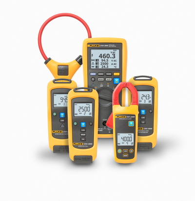
The wireless system simplifies troubleshooting by enabling up to 10 simultaneous electrical and temperature wireless measurements. It is the first set of test tools that wirelessly connects multiple measurement modules and sends simultaneous readings to a master device up to 20 m away.
The customisable tool set lets users choose various measurement modules based on their specific troubleshooting needs.
At the core of the system is a CAT III 1000 V/CAT IV 600 V multimeter with a screen that displays its readings along with live readings from up to three other measurement modules. For more complex troubleshooting, users can view live measurements from up to 10 modules simultaneously on a computer equipped with the CNX PC adapter.
The modules, which include AC voltage, AC current clamp, iFlex AC current clamp and K-type temperature units, can take live measurements or log up to 65,000 sets of data. Logged data can be saved to a computer in .csv format.
The system allows users to place modules in hazardous or awkward places and observe the readings from a safe distance. For example, technicians can de-energise a panel, connect voltage or current modules to all three phases and close and re-energise the panel. The measurements can then be read outside the arc flash zone.
By using the most common electrical test tool, the multimeter, the wireless system lets technicians extend their capabilities and skills, helping them meet the demands for more complex three-phase work without retraining on more complex test tools.
Bill Wedge, president of Wedge Electric, in California, said: “To troubleshoot an intermittent motor overload condition - providing the motor is not faulty - I would connect the wireless voltage module of the Fluke CNX Wireless system to the motor starter within the motor control centre, the wireless current module in the field disconnect switch adjacent to the motor and the temperature module at the motor.
“I could then verify and view the supply voltage, current and temperature all on the central multimeter while it was operating.”
He said further evaluation would be required to isolate the cause of the problem, but one person could narrow the variables down quickly. The modules could be left in place and periodically viewed and logged by one person or multiple personnel within different shifts, and/or modules left in place to auto log data and download later for review.
“To commission an air handler unit, you would connect the voltage module to the supply fan overcurrent protective device, the current module to the supply fan ‘T’ leads at the variable frequency drive and secure the temperature module in the discharge air plenum or adjacent to the discharge air sensor.
“Multiple operation parameters could be simultaneously verified, simplifying calibrating the 0-10 VDC analog input signal from the discharge air sensor to the drive for supply fan speed reference.
“To troubleshoot a sporadic extruder barrel heater zone where multiple control enclosures are located on different floors of a three-level platform, you would connect the voltage module to the silicon controlled rectifier for the suspect zone, the current module to the heater load conductors and the temperature module to the barrel zone heater. Since measurements could be obtained at any level of the platform, one person, instead of two or three, could collect them.
The personal protective equipment (PPE) required by modern safety standards, while important, inherently adds risks through loss of dexterity and colour impairment from the yellow shield, which requires a flashlight to distinguish between blue and green ‘conductors’.
While power should always be de-energised with lock-out/tag-out provisions, it’s not always possible. The wireless system modules could be connected to potentially dangerous voltage, safely guarded behind closed panel doors and monitored with vastly reduced exposure to hazardous conditions.
Digital twin approach to continuous emissions monitoring
Endress + Hauser has developed digital twin software that maintains emissions monitoring during...
Chip-scale magnetometer for high-precision magnetic sensing
Researchers have developed a magnetometer fully integrated onto a chip, offering high sensitivity...
Turning RFID tags into scalable passive sensors
Researchers from UC San Diego have used low-cost RFID tags to develop analog passive sensors that...
")

