
Throwing some light on electromagnetic fields
The advent of compact fluorescent lamps (CFLs) and their increasing adoption has brought about the necessity to test for the effect of electromagnetic fields on humans.
The European standards that apply are a part of the low voltage directive. One part of the exposure is based on magnetic and electric field coupling between lighting equipment and person.
The interaction of time-varying electric fields with the human body results in the flow of electric charges (electric current), the polarisation of bound charge (formation of electric dipoles) and the reorientation of electric dipoles already present in tissue.
The relative magnitudes of these different effects depend on the electrical properties of the body - that is, electrical conductivity (governing the flow of electric current) and permittivity (governing the magnitude of polarisation effects).
Electrical conductivity and permittivity vary with the type of body tissue and also depend on the frequency of the applied field. Electric fields external to the body induce a surface charge on the body. This results in induced currents in the body, the distribution of which depends on exposure conditions, on the size and shape of the body and on the body’s position in the field.
CFLs have been designed to replace incandescent light bulbs. The principle of operation of the CFL can be described in three steps.
The first is the conversion of the 50 Hz signal to a higher frequency signal (typically 25 - 70 kHz) using an electronic ballast at the base of the bulb. Conversion to a higher frequency eliminates light flicker and improves the efficiency of the bulb.
The second step is the excitation of mercury atoms in the tube by the higher frequency signal. Excited mercury atoms emit photons at ultraviolet frequencies, which are not visible to the human eye.
This requires a third step, which is the use of fluorescence to create visible light. A phosphor coating on the tube absorbs UV light and emits photons in the visible spectrum.
The biological effect of electromagnetic fields is to cause dielectric heating. This heating effect varies with the power and the frequency of the electromagnetic energy. A measure of the heating effect is the specific absorption rate or SAR, which has units of watts per kilogram (W/kg).
The established safety limits for exposure to various frequencies of electromagnetic energy based on SAR, are mainly based on International Commission on Non-Ionozing Radiation Protection (ICNIRP) guidelines,which guard against thermal damage.
For sinusoidal fields at frequencies below about 10 MHz, the magnitude of the induced current density inside the body increases with frequency. The induced current density distribution varies inversely with the body cross-section and may be relatively high in the neck and ankles.
The reference levels for the electric and magnetic fields should be considered separately and not additively.
The AFJ VDH 30 Van Der Hoofden test system allows the determination of human exposure to radiation caused by luminaires into the frequency range from 20 kHz to 10 MHz. The measurement is based on IEC 62493 (IEC 34/116/CD:2008) and takes account of near, transitional and far-field effects.
The Van Der Hoofden test head consists of three elements - an electrically conductive sphere with a diameter of 210 mm, a connection line of 300 mm long and a protection network for the EMI receiver.
The test head is mounted on an insulated mast system with height adjustment. The EMI receiver measures a voltage across 50 Ω.
It must be connected to the BNC connector of the mast clamp. To determine the compliance of a luminaire to the standard, the measured voltages must be converted into induced current densities. The measured densities must be expressed in relation to the allowed densities as defined by the standard.
The interposing circuit between the Van der Hoofden test head and receiver is shown in Figure 1.
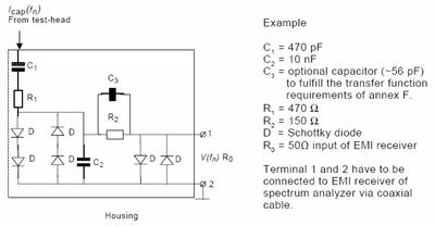
The transfer function for this circuit is:
G(fn) = V(fn)/Icap(fn) = Ro/√(1+{[Ro+R2].2π.f(n).C2}2)
Using the transfer function, current density is calculated by:
Jcap (fn) = V(fn)/{G(fn).Aneck} where Aneck = 0.112. π/4
Using the AFJ receiver, measurements are made in the frequency range of 20 to 150 kHz, and in the range of 150 kHz to 10 MHz, using the peak detector. The AFJ receivers are equipped with appropriate software to perform the above calculations and to enter the permissible current density factors under the standard.
Novel technique to shield 2D materials from vibrations
Researchers from Monash University have demonstrated a new way to protect atomically thin...
What's the difference between traditional resins and bio-based resins?
Two Electrolube resin specialists have collaborated to explain how introducing bio-based resin...
Waterproof connectors and enclosures: check what protection you need
Every electronic device needs some kind of protection, depending on where and how it will be used.


")