
The ideal filter in just 6 steps

The causes of EMC interference can be numerous; therefore, standard filters are not always the simplest and best solution. SCHURTER now offers an evaluation board with which an almost ideal filter for the specific incident can be built within a short time in an iterative process.
Every developer of an electrical or electronic device is faced with the same problem: in the end, the device must comply with international EMC guidelines regarding emissions and immunity. In the age of the substitution of mechanical and mechatronic systems by purely electrical ones, EMC is becoming increasingly important.
Origin
EMC problems, often of an unpredictable nature, mostly arise in the power section. Like most electronic assemblies, the power section is also increasingly being mounted on printed circuit boards with discrete components. Due to the high integration of components to achieve a compact design, thermal problems can arise due to high currents on the printed circuit board. The resulting EMC interference can affect adjacent components due to the lack of spatial separation. Therefore, a compact filter directly on the PCB with discrete components is often the best solution. And a current compensated choke with capacitors is the most efficient measure in EMC suppression.
Nothing goes without measurements
The ones who can carry out EMC measurements themselves according to EN 55011 should take a closer look at the DKIH Evaluation Boards. Variants of the boards are available for one-phase and three-phase systems. These evaluation boards are suitable for systems up to 50 ampères.
Filter design
An EMC filter should bring the emissions below the limits specified for the application. Most product standards require measurements in the range from 150 kHz to 30 MHz conducted and 30 to 1000 MHz radiated. Line filters are often required to ensure EMC-compliant operation. Classical LC filters consist of a combination of interference protection capacitors and suppression chokes. The choke is typically designed as a current-compensated choke with two opposing windings and the same number of turns. This compensates for the magnetic fields, which means that the normal operating current does not see any inductance.
A diagram of a typical one-phase filter can be seen below, with a current compensated choke and two X capacitors between L and N and two Y capacitors to ground. This circuit is very effective with low power dissipation, but provides good noise attenuation over a wide frequency range.

Measurement at the real interferer
The universal design allows the construction of a classic LC filter circuit. Two X capacitors of various sizes can be installed before and after the choke and a total of four Y capacitors. Leakage resistors are provided to protect against electric shock. The connection is made via two 6.3 x 0.8 mm tabs, a 4 mm hole or direct soldering of the cables to the large-surface pads. It is recommended to make the earth connection as flat as possible using copper tape or wide copper strands. The effect of the Y capacitors is considerably influenced by the connection.

If no previous measurements or simulations have been made, it is usually not known whether we are dealing with a high asymmetrical (L/N to PE) or symmetrical (L to N) interference.
It is always advisable to make a measurement first without filter components on the device. It must be ensured that the maximum interference level is found. This is decisive for EMC conformity.
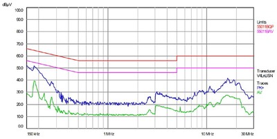
Step 1
Measurement without filter components, conducted at 150 kHz-30 MHz

- The limit values are clearly exceeded.
Step 2
Configuration of the Evaluation Board DKIH1-EVB with choke 0.8 mH (10 A ferrite) and capacities of 2 x 470 nF and 4 x 2.2 nF

- Insufficient suppression, especially in the lower frequency range
- Larger X capacitors can be used to increase suppression in the lower range
Step 3
Configuration of the evaluation board DKIH1-EVB with choke 0.8 mH (10 A ferrite) and larger X capacitors of 2 x 1 μF and 4 x 2.2 nF

- Still slightly insufficient suppression despite larger X capacitors.
- A replacement of the choke with ferrite core by a choke with nanocrystalline core with much higher inductance (6.9 mH instead of 0.8 mH) is required.
Step 4
Configuration of the evaluation board DKIH1-EVB with nanocrystalline choke 6.9 mH (10 A NK), capacitors remain at 2 x 1 μF and 4 x 2.2 nF

- Only slightly insufficient suppression due to the higher inductance.
- Filter effect not yet optimal.
Step 5
Configuration of the Evaluation Board DKIH1-EVB 6.9 mH (10 A NK), X capacitors increased to 2 x 2.2 μF, Y capacitors remain at 4 x 2.2 nF

- Very good suppression thanks to larger X capacitors
- Circuit can still be cost- and space-optimised
Step 6
Configuration of the evaluation board DKIH1-EVB with ferrite choke 0.8 mH (10 A ferrite), capacitors remain the same at 2 x 2.2 μF, 4 x 2.2 nF
- In this example the amount of asymmetric interference is not very large, so that the inductance can be reduced.
- Cost-optimised circuit with large X capacitors instead of expensive nanocrystalline chokes.
Before implementation
If a suitable circuit is found on the evaluation board, some questions have to be considered before the circuit is implemented on the device board:
- Mass connection of the Y capacitors
- Leakage current of the Y capacitors
- Heating of the choke (measure temperature at critical load current)
- Space requirement of the components
- Is the temperature rating of the components sufficient?
- Are the voltage ratings of the capacitors sufficient?
- Do the capacitors meet the common safety requirements for the mains voltage used? The IEC standards generally require the use of safety capacitors of at least class X2 and Y2 for 250 VAC applications.
- High voltage requirements on the capacitors?
Especially the leakage currents are often critical due to application or standard requirements. It is recommended to measure the currents of the entire system with a built-in filter circuit.
The normal leakage currents of the capacitors used can be easily calculated: IL = 2π · fn · Un · Cy
Conclusion
Thanks to the SCHURTER DKIH Evaluation Boards, various filter configurations can be quickly measured without changes to the PCB layout. With high L and C component values, the vast majority of interferences can be adequately attenuated.
But the art of optimal filter design is to find the right component combination. Often somewhat smaller C and L values are sufficient, if they are combined optimally. It is recommended to remeasure the finished application with the final filter design on the circuit board. An EMC measurement of the finished system or device is indispensable for the declaration of conformity.
In case of questions and measuring problems, SCHURTER’s EMC-Service is at your disposal.
About SCHURTER
SCHURTER continues to be a progressive innovator and manufacturer of electronic and electrical components worldwide. Our products ensure safe and clean supply of power, while making equipment easy to use.
Originally published here.
Modern jamming: drones, quantum and AI
Modern defence requires modern jamming — this article introduces the latest electronic...
Conformal coatings: challenges and considerations 101
Conformal coating has become an integral part of the PCB production process for some...
Overtemperature protection for power semiconductors
SCHURTER reintroduces its RTS (Reflowable Thermal Switch) — a particularly compact...


