
Hall sensors — how to check their operation

Find out how to test popular switches.
In the majority of popular applications, Hall sensors are used as non-contact switches. Systems in SIP3 packages that contain complete circuits for signal conditioning with a two-mode output are mainly used for this function. Therefore, this is not so much a sensor as it is a Hall switch. Operation of such a system can be easily checked if we know the system’s type. When we deal with an unidentified element, we should have at least some basic knowledge of how a Hall sensor works in order to be able to check the system’s operation. A set of necessary information is provided in this article.
Hall sensor — basic information
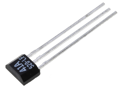
The majority of Hall switches in TO-92 or TO-92UA SIP3 packages feature the following output arrangement: 1 — Vdd (power supply), 2 — chassis ground, 3 — output. They are numbered in the same way as in the transistor. Things become a bit more complicated when it comes to SMD sensors, because here you can encounter SOT-23, SOT-223, SO-8 or other, special-purpose packages.
While SOT-23 and SOT-223 packages are well-known from transistors and their pinout corresponds to the arrangement of outputs mentioned above, the same cannot be said about other types of packages. Without access to the Hall sensor documentation or at least the name of its manufacturer, it is hard to determine which terminals are responsible for powering or connecting the sensor interface.
It was integration of a conditioning system, a Schmitt trigger and an output amplifier in a single sensor package that made Hall sensors, which are sometimes called Hall-effect sensors, popular and enabled the application of those systems as magnetic field detectors in the industry. However, when we deal with a two-mode (enabled/disabled) output, we should talk not so much about a Hall sensor as about a Hall switch, although these terms are often confused and mixed not only by users, but also in manufacturers’ catalogues.
Hall switches can work in the following modes:
Bipolar Hall sensor
Magnetic field of proper voltage and north or south polarity is required to change a switch output state. If a sensor is placed in such a field, its output changes its state and maintains it until moved to a field of opposite polarity. It is said that those systems have a latch output.
Unipolar positive Hall sensor
The output of that switch is activated by a properly strong positive magnetic field (‘S’ pole). The output is deactivated if that field fades (reaches a value that is below the switch-on threshold).
Unipolar negative Hall sensor
The output of that switch is activated by a properly strong negative magnetic field (‘N’ pole). The output is deactivated if that field fades (reaches a value that is below the switch-on threshold).
How to check the operation of a Hall sensor
In order to check a sensor it is enough to be aware of the Hall effect and have a power supply or a battery and a strong magnet. Firstly, connect the positive polarity voltage to terminal 1, and then connect the negative supply pole to terminal 2. You can estimate value of the supply voltage based on the switch application. Those in miniature packages that are intended for portable devices have a supply voltage of 3 V. The voltage of bigger switches, which are used in the industry, ranges from 5 to 12 V. Unfortunately, this is not a rule and without detailed information from a technical data sheet it should be taken into account that experimenting with supply voltage can lead to damage of a switch system or will not guarantee its sufficient sensitivity.
After applying supply voltage between the free terminal of a Hall sensor and the ground chassis, turn on the voltmeter. Now, bring one of strong magnet’s poles close to the front of a sensor, keeping it at the right angle. Depending on a switch type, voltage on its output should change rapidly either when the sensor is approached by the ‘S’ or ‘N’ pole. In the case of a bipolar switch, this effect can be achieved by bringing close/distancing, rotating (changing the polarity) and bringing close/distancing again of one of magnetic poles. If the voltage change meets our expectations, the switch presumably works properly and is ready to use.


Application and installation of a Hall sensor
After checking the functioning of a Hall-effect sensor, we can proceed to its target application. It is worth following a couple of basic principles.
The output signal from a Hall sensor changes depending on the sine of the angle between the sensor’s surface and the resultant vector of the magnetic field intensity. Maximum and minimum signals are reached when the lines of the magnetic field force are perpendicular or parallel to the sensor’s surface, respectively. Manufacturers calibrate sensors in perfect conditions, so in real applications potential errors that result from the angle of installation of a Hall switch system with respect to the lines of the magnetic field force should be taken into account.
It is also important to choose a Hall switch that is compatible with the magnet or vice versa. In certain applications, for example while setting the position of a spinning object, it may happen that the output signal is already available when the magnet is only approaching the system’s casing, and not when it is precisely under the casing.
Even though modern Hall sensors work in a very wide temperature range, it can still have a strong impact on their parameters. It is therefore worth paying attention to the temperature range of the environment in which a Hall switch will be used when choosing it for a given application.
It is also beneficial to notice the limitation of the load’s amperage. Not every Hall switch is suitable for switching on a transmitter or a signalling light. Some have a low output load that is suitable for powering a CMOS or TTL system input. It should be remembered that the load current directly affects the temperature of the switch structure and hence its sensitivity parameter.
Selection of packages and their types should be application-specific. The TO-92 package of a Hall sensor is rather fragile and easy to damage. It is also easy to disconnect the delicate terminals. That is why while installing a switch system in your application, especially on a long cable, proper security of its terminals should be ensured, for example, by means of soldering the switch on a PCB or attaching the cable to the cover in a proper way.
Battery-free smart home sensors developed using metal tags
Researchers at Georgia Tech have developed battery-free ultrasonic sensors that use passive tags...
Ultrasound wristband enables precise robotic hand control
By moving their hands and fingers, users can direct a robot to play piano or shoot a basketball,...
Fingertip bandage brings texture to touchscreens
Researchers have developed a haptic device that enables wearers to feel virtual textures and...


")